
Characterization of a micro heat exchanger (air water cooler)
The estimation of the characteristic quantities of a micro heat exchanger may be done experimentally or by a numerical simulation. For example with a computer code like FLUENT. The experimental results are usually the measured integral physical quantities at the inlet and outlet of the device. In contrast to the experiment, the numerical simulation is able to describe mathematically the single physical effects inside the micro channels, to obtain a better understanding of the flow and heat transfer processes.
Due to the different thermal diffusivity, a laminar air stream through a micro channel will be heated up faster than a liquid flow. For this reason, the micro channels of the air passage of an air water cooler must be shorter than the micro channels of the water passage. The air water cooler, which is shown in Figure 1, was designed on the basis of the above considerations. The device, a micro heat exchanger in cross flow, was manufactured of several structured metal foils.
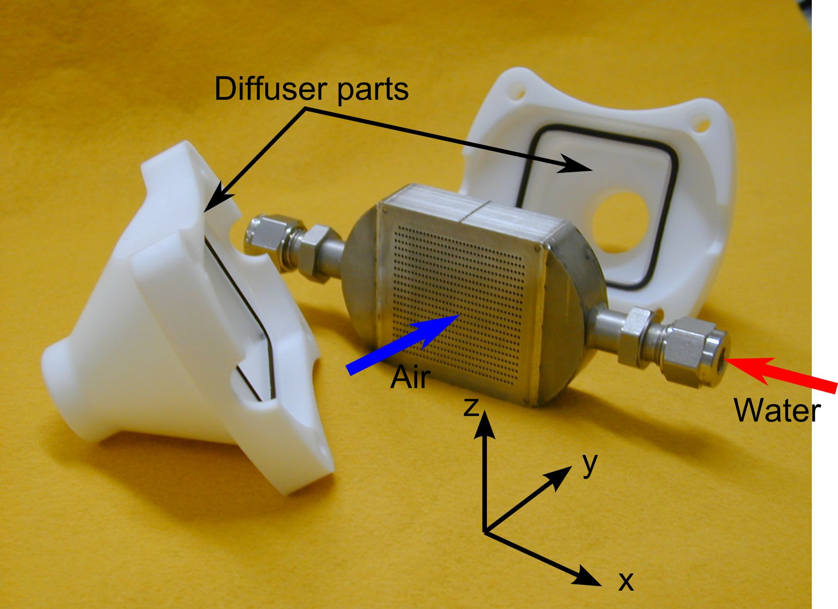 Figure 1: Air-Water-Heat-Exchanger
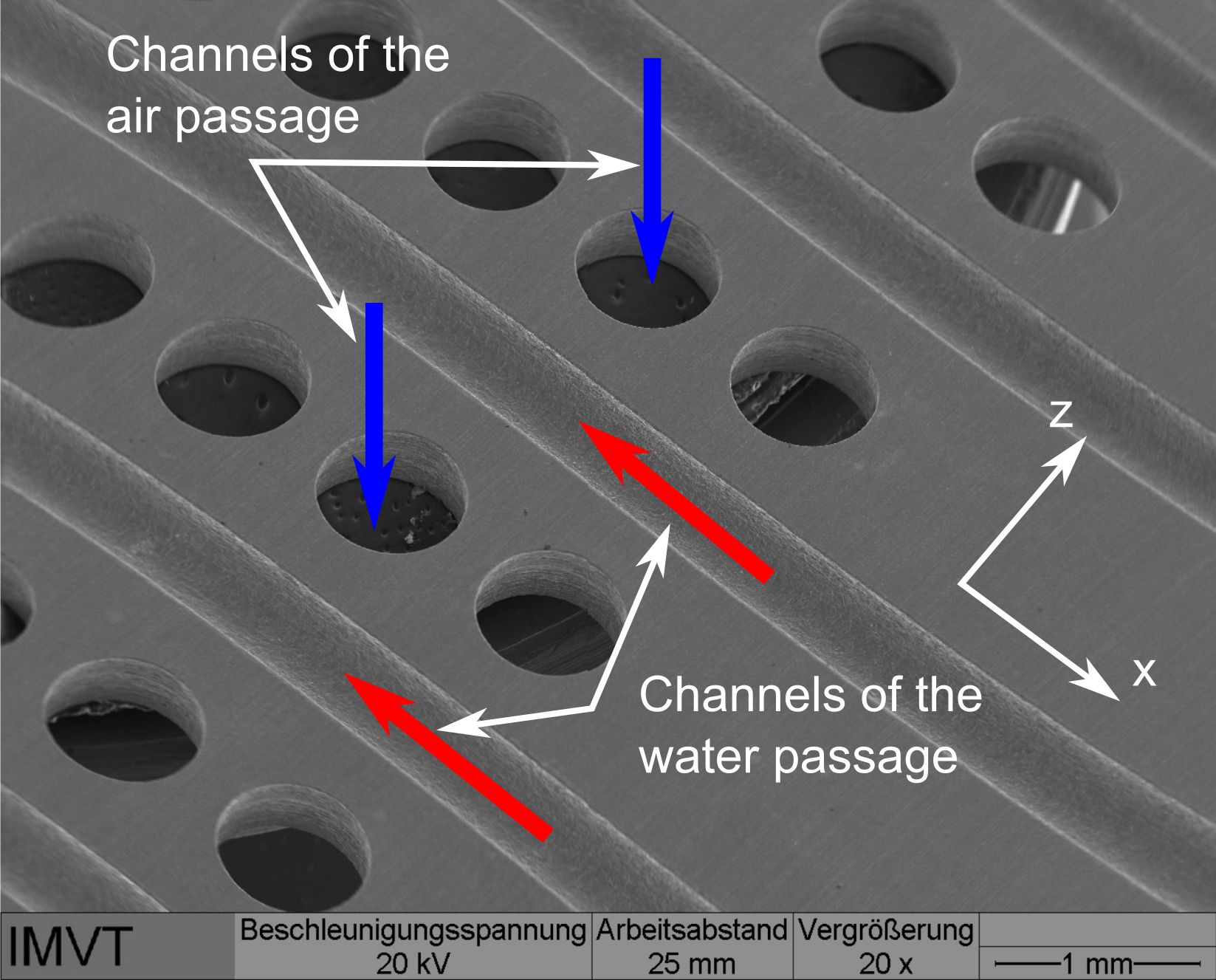 Figure 2: REM-Image of a metallic foil manufactured by the chemical wet etching
Figure 2 show details of such a metal foil, which was structured by chemical wet etching. The circular openings with a diameter of 0.35 mm are the micro channels of the air passage. Between these openings the micro channels of the water passage are arranged. Base on the structuring process the flow cross section of these micro channels have the shape of a half ellipse. Many of such structured foils were stacked on top of each other. The foil stack is then diffusion bonded to generate a leak-tight connection between the foils. The tube connections for the air and the water were laser welded to the base body.
As outlined in Figure 3, for the 3D numerical simulation of the flow and heat transfer processes inside the micro channels only two foils were modelled. The air flows through the top sheet and the water through to the lower one. In the mathematical model symmetry conditions were utilized. Therefore the micro channels of the air passage have a shape of a semicircle and the micro channels on the water passage have the shape of a quarter-ellipse. The heat transfer by conduction between both foils was realized by an "INTERFACE" boundary condition, which is available in FLUENT.
Figure 4 show exemplary one result of the numerical calculations. The temperature distribution of the air passage on the centre plane of the micro channels. For this selected operating point the calculated temperature distribution is uniform. The heating of the air stream in each micro channel is almost identical. The agreement between the measured and calculated outlet temperatures in Figure 4 is sufficiently good.
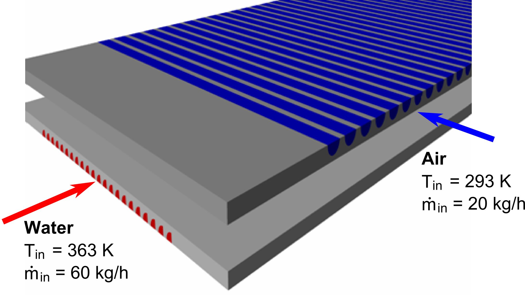 Figure 3: FLUENT Model consisting of two foils
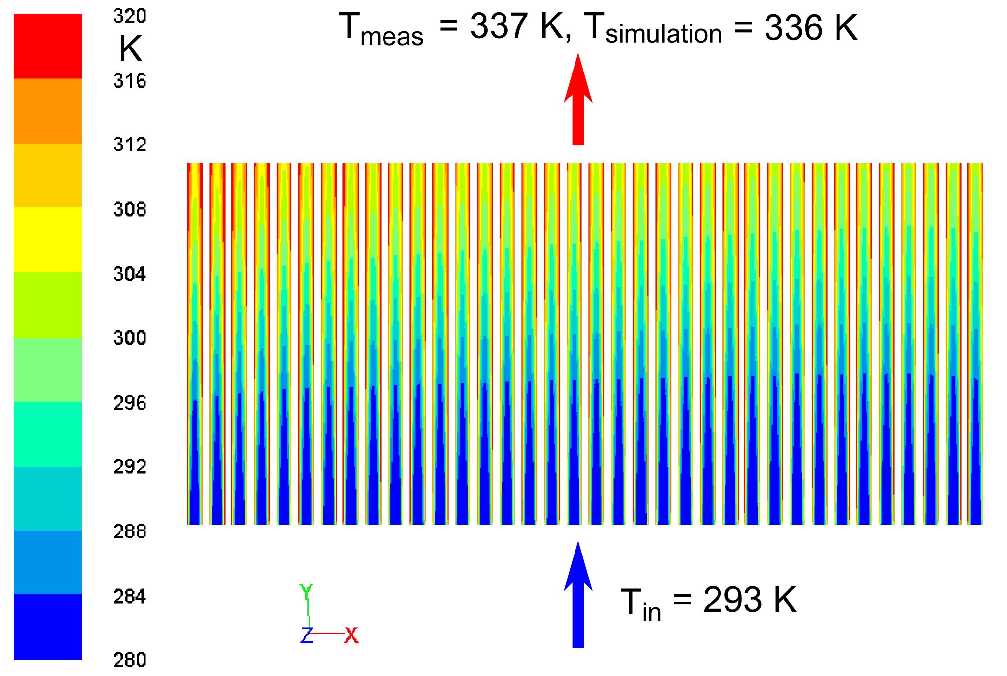 Figure 4: Temperature distribution inside the micro channels of the air passage (Re = 770 und Ma = 0.1)